 The
XJR-14’s monocoque didn't have the usual piercings in the structure for
doors. Through a clever rules interpretation, though following on
the Peugeot 905’s coattails, the side windows were hinged and
subsequently this is how the driver entered and exited the car,
allowing for a much stiffer monocoque.
The
XJR-14’s monocoque didn't have the usual piercings in the structure for
doors. Through a clever rules interpretation, though following on
the Peugeot 905’s coattails, the side windows were hinged and
subsequently this is how the driver entered and exited the car,
allowing for a much stiffer monocoque. Laminated inner and outer skins of carbon fiber twill with aluminum honeycomb in between, in addition to loads of unidirectional carbon fiber, the XJR-14’s tub was laid up in female molds and in two pieces, a top and a bottom. The tub halves were then glued together but not before carbon bulkheads were inserted.
The completed tub weighed around 100 lbs (45-47 kgs) and in house torsion testing showed approximately 80,000 lbs per degree of torsional rigidity.
The XJR-14's roll over hoop was steel and bolted to hard points located at the corners of the cockpit opening.
 The
Jaguar's short front overhang meant the main crash box was
shorter than desired and subsequently the XJR-14 struggled a bit to
pass FISA's crash test. But FISA's regulations, which weren't
even particularly stringent, simply
required
that there not be any damage aft
of the pedal face. And while crash testing of the XJR-14
revealed
a crack in the tub floor that propagated past the pedal face, the
solution was relatively simple, says Steve Farrell, race engineer for
TWR (1989-1992), "The car didn't do as well as we had hoped in the
crash testing, but in the end the FIA allowed us to 'draw a line' at
the point where damage finished in the test and for us to agree that we
would always set the pedals behind this line."
The
Jaguar's short front overhang meant the main crash box was
shorter than desired and subsequently the XJR-14 struggled a bit to
pass FISA's crash test. But FISA's regulations, which weren't
even particularly stringent, simply
required
that there not be any damage aft
of the pedal face. And while crash testing of the XJR-14
revealed
a crack in the tub floor that propagated past the pedal face, the
solution was relatively simple, says Steve Farrell, race engineer for
TWR (1989-1992), "The car didn't do as well as we had hoped in the
crash testing, but in the end the FIA allowed us to 'draw a line' at
the point where damage finished in the test and for us to agree that we
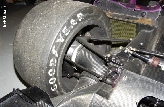
would always set the pedals behind this line." The
torsion bar suspension allows for a more compact package at the front
of the car. The rocker arm rotates on the
longitudinally
mounted torsion bar. The torsion bar itself is hidden by the
monocoque though is accessible from the front (1). The
torsion bar rotated when the pushrod moved and was connected to the pushrod via a bellcrank (2). The bar’s
resistance
to movement was determined by its diameter, wall thickness,
and
length
and thus was the equivalent spring rate.
The
torsion bar suspension allows for a more compact package at the front
of the car. The rocker arm rotates on the
longitudinally
mounted torsion bar. The torsion bar itself is hidden by the
monocoque though is accessible from the front (1). The
torsion bar rotated when the pushrod moved and was connected to the pushrod via a bellcrank (2). The bar’s
resistance
to movement was determined by its diameter, wall thickness,
and
length
and thus was the equivalent spring rate.The dampers (3) are mounted horizontally on the top of the tub, transversely across the chassis. The anti roll system (4) picks up off the bellcrank through a pushrod.
“As far as I know it was unique at that time,” says TWR Chief Designer John Piper regarding the XJR-14's torsion bar front suspension. Ultimately packaging drove the choice of the torsion bars, “it made the pushrod angle better whilst keeping the front nose height low.” This was always important in keeping frontal area to a minimum. Ride height could be altered with just a few turns of a single, centrally mounted, screw jack, and swapping out different stiffness torsion bars could be done “in seconds” making the whole system ultimately more user friendly.
If you look carefully in the image, at upper right, where the bellcrank mounts to the tub, you can see the repaired section of #591's tub caused by the 1992 accident at Lime Rock.
 The
XJR-14's brake inlets were incorporated into the structural outriggers,
the outriggers being hollow and open on the inlet end. They
bolted to the sides of the crash box. And while not part of the
crash structure per se, says John Piper, "I think Ross had hoped they
might contribute some energy dissipation, but in the end they didn’t
much."
The
XJR-14's brake inlets were incorporated into the structural outriggers,
the outriggers being hollow and open on the inlet end. They
bolted to the sides of the crash box. And while not part of the
crash structure per se, says John Piper, "I think Ross had hoped they
might contribute some energy dissipation, but in the end they didn’t
much."The headlights seem almost as an afterthought, certainly for an endurance racer. Though in its life time, the XJR-14 never contested either a 24 or 12 hour race.
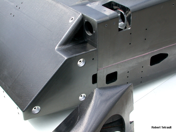 The
outriggers bolted to the side of the primary crash structure. The
round hole in the outboard face of the outrigger (just visible) is where the brake
ducting that fed directly to the upright passed out of the outrigger.
The
outriggers bolted to the side of the primary crash structure. The
round hole in the outboard face of the outrigger (just visible) is where the brake
ducting that fed directly to the upright passed out of the outrigger.You can also see here the very short impact structure.
 The
XJR-14's front brake ducting was especially
elegant. "Brake
ducting was always an afterthought on most sports cars with horrible
bits of convoluted hose that only stayed intact for a few laps." says Piper. The traditional
method of using flexible wire
hosing as brake ducting had the drawback of being susceptible to being
dislodged during the race as it was typically attached via hose clamps
and
little else.
The
XJR-14's front brake ducting was especially
elegant. "Brake
ducting was always an afterthought on most sports cars with horrible
bits of convoluted hose that only stayed intact for a few laps." says Piper. The traditional
method of using flexible wire
hosing as brake ducting had the drawback of being susceptible to being
dislodged during the race as it was typically attached via hose clamps
and
little else.
 Rigid
brake ducts fed into the
upright/brake calipers but pivoted on elbow joints (white), each
machined from a billet
of Teflon, allowing for steering input.
To allow for flex within the system bellows attached
the elbow to the
primary feed. The
bellows were held in
place by a spring. The
front pushrod
pierced the brake duct though was sealed by rubber skirts on either end.
Rigid
brake ducts fed into the
upright/brake calipers but pivoted on elbow joints (white), each
machined from a billet
of Teflon, allowing for steering input.
To allow for flex within the system bellows attached
the elbow to the
primary feed. The
bellows were held in
place by a spring. The
front pushrod
pierced the brake duct though was sealed by rubber skirts on either end. Packaging
at the front was so tight, given the need to accommodate the front wing,
as well as the crash structure, that the brake and clutch fluid
reservoirs
were moved to the front of the side pod, being accessible through a
hatch after the nose was removed.
Packaging
at the front was so tight, given the need to accommodate the front wing,
as well as the crash structure, that the brake and clutch fluid
reservoirs
were moved to the front of the side pod, being accessible through a
hatch after the nose was removed.