Pete
Lyons' fantastic Can-Am Cars in Detail:
 |
May/June 2013
Reload
to see the latest news
All news content copyright Michael J. Fuller, unless
otherwise noted |

| | >>2013 Le Mans Test & 24 Coverage<< | |  6.29.13 6.29.13
>>"Party like it's 1999!" Riley & Scott MkIII T-shirts available through Roger Warwick (roger@rogerwarrick.com). Tell him you saw it on Mulsanne's Corner!
And keeping in the spirit, here's 1999 Daytona winner, R&S MkIII chassis 02, going through the paces at Gingerman...owner Al Petkus at the wheel. Oh, yeah, that's a Ferrari 333SP up ahead... | 
|  6.20.13 6.20.13
>>File
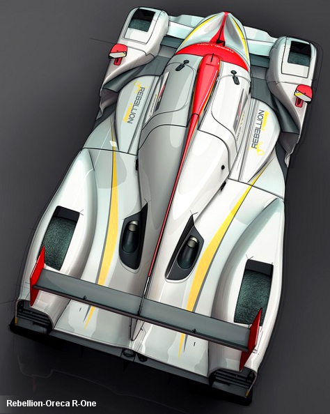
under old-news, I'm just now catching with the Rebellion announcement
that they will be fielding an Oreca-developed Rebellion R-One LMP1 next
season.
| 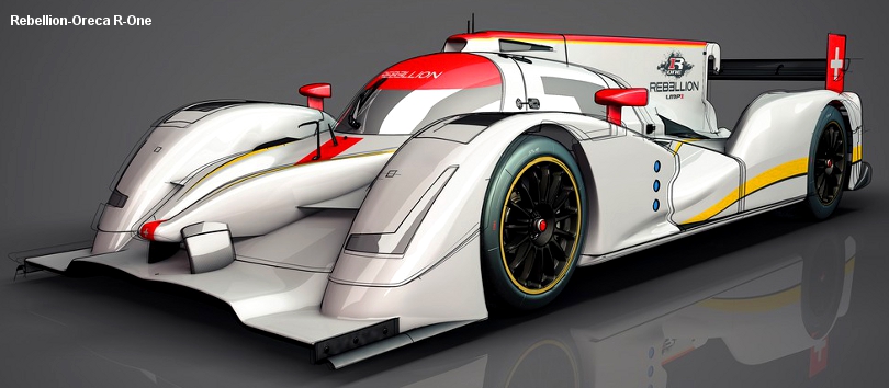 The R-one will continue Rebellion's Toyota relationship through the use of an updated version of the Toyota
RV8KLM engine. The acknowledgment of the continuing utilization of the RV8KLM engine is interesting given the changing engine
regulations for next year. The R-one will continue Rebellion's Toyota relationship through the use of an updated version of the Toyota
RV8KLM engine. The acknowledgment of the continuing utilization of the RV8KLM engine is interesting given the changing engine
regulations for next year. | 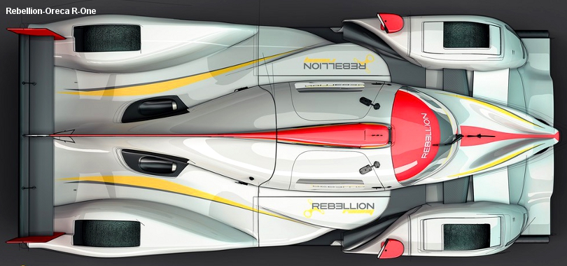 While
this is a "rendering", it is well detailed and thus based directly on
the CAD of an actual car, though there are a few details that appear to
be
carried over from the previous rules set leading one to beleive that
this could very well be a crib of the stillborn Oreca coupe LMP1
concept. While
this is a "rendering", it is well detailed and thus based directly on
the CAD of an actual car, though there are a few details that appear to
be
carried over from the previous rules set leading one to beleive that
this could very well be a crib of the stillborn Oreca coupe LMP1
concept.
Naturally most people will also notice the narrow span rear wing.
And
I'm not sure that the monocoque is 2014 compliant (it could be, but it
looks a bit "aggressive" regarding it's trailing edge height). |  Interesting
details? I really like the side pod detailing, how the radiator inlet
is prominent and the outboard portion of the side pod is drastically
reduced in height. Interesting
details? I really like the side pod detailing, how the radiator inlet
is prominent and the outboard portion of the side pod is drastically
reduced in height. |
|  6.12.13 6.12.13
>>It's
been a while since we've had a Porsche to talk about, much less draw
on! In an effort to mask certain details Porsche has gone with an
interesting Dazzle Ship paint job as well as only releasing carefully
chosen angles. But it gets everyone talking and gives the 1/43
model makers one more livery to sell...
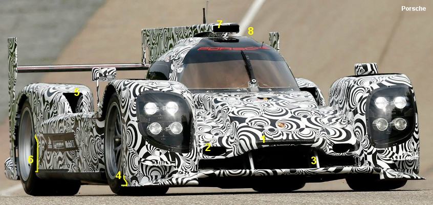
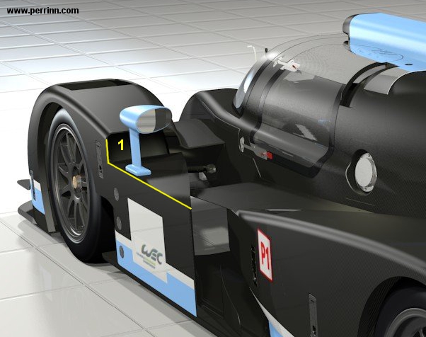
The Porsche LMP1 (type
name unknown for the moment) is a 2014 rules car thus some features are
new; narrow width (1900 mm), full width rear wing, etc. And while
few technical details are
known, we do know that the car will utilize a hybrid system and the
expectation is that it will be mounted forward in the chassis with
evidence being the cooling inlet slot in the nose (1). With the
elimination of the regulation that governed the speed when a front
mounted system could release its power (only above 120 km/h) it
can be expected that the trend would revert to favoring front
located hybrid systems from a desire to optimize weight
distribution.
The Porsche's brakes are cooled by brake
ducts (2) either side of the nosebox and the front wing hangs from the
nosebox via simple posts (3). Yes, this is the "open" splitter
concept; but remember that the 2014 regulations have changed regarding
those non-wing wings and the days of diffusers are more than likely
gone given the efficiency advantage of a front wing setup. Some
will decry this, front wings don't belong on a sportscar after all, but
the ACO sees this also as a way to further improve the historic
sportscar front balance issue. At the outboard edge of the front
splitter is an interesting undercut (4).
Rear
brakes appear to be cooled by a ducts in the rear fenders (5) and
Porsche has offset the sidepod inboard slightly down the length of the
wheelbase freeing up a slight outboard 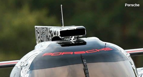 "edge"
(6). It's no "ankle cutter" (see the Jaguar XJR-10 for a more
appropriate example), but just another interesting detail if nothing
more. "edge"
(6). It's no "ankle cutter" (see the Jaguar XJR-10 for a more
appropriate example), but just another interesting detail if nothing
more.
Porsche has opted for a squat and rectangular engine intake (7).
One
of the bigger regulation changes for 2014 is the increase in height for
the front and rear roll over structures. I've mentioned this a
bit in the write up for the Perrinn LMP1 (below). The front roll
over hoop is now 950 mm tall, the rear 935 mm. The increase at
the front is a mere 30 mm compared to current regulations (little over
1"), but there is an element of interpretation as the regulation also seems
to state that the 950 mm height must maintained for 300 mm in the X
dimension (front view) for the front hoop rollover hoop and at the rear
the 935 mm height must be maintained for 400 mm in X. With that
in mind, Porsche has created a stepped roof shape in order to
accommodate the roll over hoop dimensions (8). At the moment,
Porsche's interpretation hasn't been universally accepted.
So, the Porsche has rolled out early. Will it evolve as they get into their test program? Absolutely...
|
|  6.10.13 6.10.13
>>So I talked about the "Longtail" R18 a few weeks ago. And amongst all my grumpy blather, the most important take away from all that isn't
that the rear bodywork moved rearwards to end on the same plane in the
Y dimension as the wing and endplates, but that the diffuser moved as
well. Recall that the regulations effectively state that the
trailing edge of the bodywork must end in the same Y plane as the
diffuser (or vice versa if you prefer).
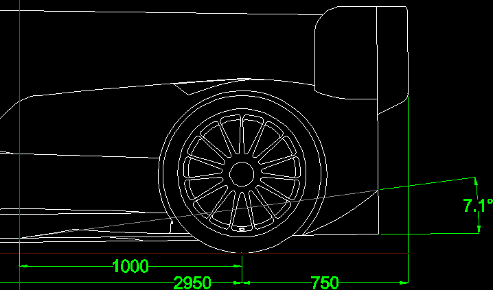
So to left I've
sketched out the "Shorttail" R18. The rear wing ends at the 750
mm max rear overhang and the bodywork proper is offset forwards an
amount from the Y plane end point of the rear wing endplates (the
offset is right around 130-140 mm, the exact dimension isn't too
important). Looking at the regulations we also know one other
thing, the leading edge of the diffuser starts 1000 mm ahead of the
rear wheel centerline and that its height above the reference plane is
a maximum of 200 mm. Of course I'm assuming Audi has drawn their
diffuser to these maximums, but I have no reason to believe otherwise
and no evidence to the contrary.
From those knowns it's a
simple matter of sketching all that out and snapping an angle to
determine the diffuser's angle and we see Audi's is at a little over 7
degrees. | 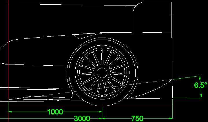 Sketching
out the "Longtail" R18 using the same knowns and recalculating the
diffuser angle and we see an angle reduction of .6 degrees.
The significance? The reduced angle diffuser produces less
drag, but also less downforce. In the end it's something you'd
look at when wanting to shed a bit more drag with the downforce loss
being insignificant. Sketching
out the "Longtail" R18 using the same knowns and recalculating the
diffuser angle and we see an angle reduction of .6 degrees.
The significance? The reduced angle diffuser produces less
drag, but also less downforce. In the end it's something you'd
look at when wanting to shed a bit more drag with the downforce loss
being insignificant.
The other thing to note, I'm told
that the R18's wheelbase was increased this season by 50 mm pushing it
out to 3000 mm, meaning the R18 and TS030 share the same major
dimensions (WB, FOH, ROH). That puts the rear wing out a little
bit further, but as you can see this doesn't affect the diffuser's
dimensions as the diffuser's location is anchored around the rear wheel
centerline; its location relative to the WB doesn't have any bearing on
the dimensions that define it. | | 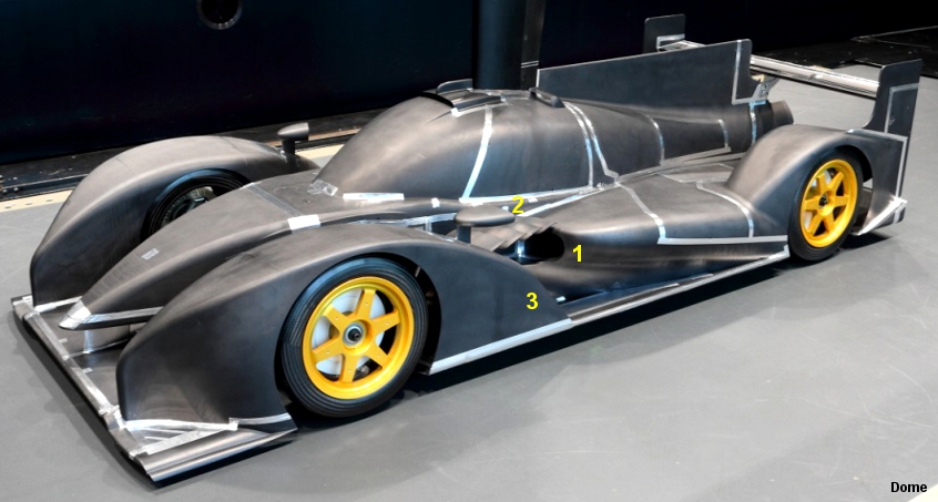 5.28.13 5.28.13
>>Dome
recently promised news regarding their ACO2014 rules S103 by June 1,
and good to their promise it hit the in-box this morning. Now
this is the first iteration wind tunnel model, so it's more than
guaranteed that the car will evolve.
First thing to notice is
the revised sidepod leading edge and inlet area (1). It's much
more aggressive in appearance and the start of the leading edge is
further back in the wheelbase. The inlet is covered by a heavily
louvered panel as well (2).
Notice how the trailing edge of
the front pontoon fender dives away pretty quickly (3). This is a
result of the vision templates. On the Perrinn LMP1 (below) they
opted to notch a section of the fender out, on the Dome they've simply
run the fender TE down to the floor sooner. | 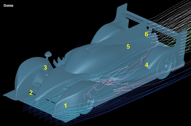 Switching
to the accompanying CFD image; it makes some of the front end details
clearer. The leading edge shape of the front fenders (1) is very
striking. A front wing and flap assembly is also apparent (2).
The front suspension is shrouded and exposed to the air stream
(3). Given the front fender shape and the minimalist front
suspension covering it's pretty clear that the concept is to move
airflow inboard to flow over the front wing assembly. Switching
to the accompanying CFD image; it makes some of the front end details
clearer. The leading edge shape of the front fenders (1) is very
striking. A front wing and flap assembly is also apparent (2).
The front suspension is shrouded and exposed to the air stream
(3). Given the front fender shape and the minimalist front
suspension covering it's pretty clear that the concept is to move
airflow inboard to flow over the front wing assembly.
Many of
the changes in the rear seem to primarily be relative changes compared
to the S102.5; shorter rear fender leading edge (4), broader cockpit
trailing edge shape (5) in lieu of new regulations regarding the roll
over hoop heights (see Perrinn LMP1 discussion below for more details).
Interestingly it seems Dome has adopted a bottom mount
for the rear wing (6), moving away from the swan neck? Swan necks
were adopted because of the reductions in wing chord promoted an
increase in wing chamber and Angle of Attack which resulted in flow
separations around the traditional lower mounts. But perhaps AoAs
are reduced with a drive towards lower total drag, and thus swan necks
are redundant? |  This
image accompanied the above shots and seems to indicate the S103 will
continue the S102.5's forward shifted weight philosophy (similar to
Audi's, as Dome so helpfully shows here as a comparison). Or...the
graphic speaks to a LMP2 version and this could just be a sales brochure for the
S102.5 as a LMP2. None of the (albeit brief) text that came with
the images addressed this graphic in particular. This
image accompanied the above shots and seems to indicate the S103 will
continue the S102.5's forward shifted weight philosophy (similar to
Audi's, as Dome so helpfully shows here as a comparison). Or...the
graphic speaks to a LMP2 version and this could just be a sales brochure for the
S102.5 as a LMP2. None of the (albeit brief) text that came with
the images addressed this graphic in particular. | | 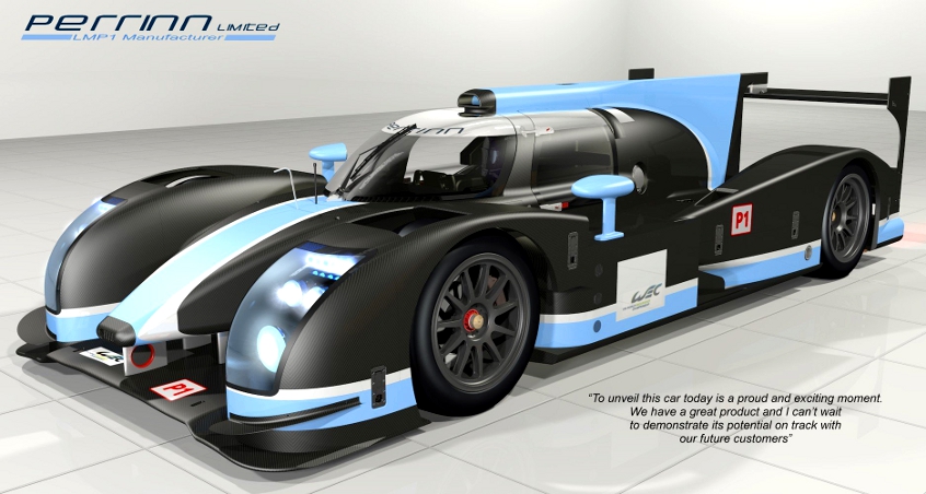 5.22.13 5.22.13
>>Nicolas
Perrin (note only one trailing edge 'n', two for “Perrin'n' LMP”)
doesn't like to talk about the Pescarolo 03. I know, I've been
hounding him about it for over a year now. It's understandable,
to an extent, but even “failures” (and I'd very much dispute that
characterization. “Rushed” perhaps...) have interesting
stories. And I am very much a fan of improvisational engineering,
recall the 03's starting point was an AMR-One monocoque...anyhow, for
over a year I'd shoot an email every 4 months or so, just to see what
was up. And for most of those replies it was a fairly typical,
“I'm working on something but it's not ready to be made public.”
I'll believe it when I see it, well that's at least what I was
thinking. Well today Perrin went public with what he and his
design team have been up to.
Now, everyone will very much
know I'm a realist who generally wears grumpy pants. I have
little patience for “fan bois” or eternal optimists (Fuck off, all of
you. Yes, you.). So I will be the first to point out that
what we're looking at here is a “virtual” car. Yes, it's digital,
nothing physical exists at the moment. And it was here I started
my inquiry, because a CAD concept rendering can be generated some what
quickly, even something that looks like a reasonable amount of thought
has gone into it. But what's generally lacking is what's called
“detail design.” Detail design is the grunt CAD work that defines
even the smallest bracket, calls out hole sizes, dimensions, part
thickness, and even composite layup. Perrin has indicated the
LMP1's design is complete and that the tooling design for manufacturing
is actually underway. So what we're looking at is much more than
a concept rendering. Now a lot of things have to go right before
we'll see a rolling chassis, but on the other hand we're not looking at
vaporware either; this is ready to roll. BTW, seen any other
ACO2014 cars lately? Yeah, thought not, a plethora of choices
doesn't exactly abound (Lotus not withstanding, no announcements from
Zytek, Oak, HPD, Oreca, Dome, Lola's dead, etc). Maybe that will
change, and maybe even change in the near future. But with less
than a year to the start of the 2014 season, a privateer would be doing
some serious head scratching given the lack of answers regarding what
their future chassis plans might be. Let's not forget that all
current equipment has an expiration date.
For the past two years
Nicholas Perrin and his design team have been chiseling away at their
concept. Aerodynamics metric has been via CFD and a full scale
testing program will be commenced, once the first car is
completed. Interestingly, Perrin has personally driven the
design, “We are a small team of experienced and skilled people, but it
is also true that I have done a lot of the design myself through time;
that was the intention to give to the car one clear design direction, a
bit like traditional designers have done in the past.”
So Perrin
is looking for customers, “LMP1 is gone in the U.S. (for now) but I
know some U.S. teams are very interested in P1 and might think about
racing in WEC and Le Mans. So the U.S. market is very important for us
still.” | 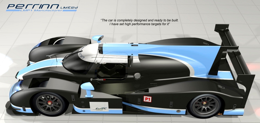 One
of the more distinctive features of the Perrinn LMP1 is the very broad
shape to the trailing edge of the cockpit, where it blends into the
engine cover. We've gotten very used to this shape dropping away
rather quickly even as the Big Honking Fin rises in the back. But
the Perrinn's trailing edge shape continues on past the point we'd
typically begin to see it fall away towards the rear of the car.
I asked Nicholas what was driving this, “(the) Bigger engine cover
comes from (the) continuity of higher and wider chassis rear roll over
structures.” ACO regulations define both a front and rear roll
over structure. For closed cars prior to ACO2014, the front
structure had dimensions defining height above the reference plane (920
mm) and a minimum separation between it and the rear roll over
structure (600 mm). However, the height of the rear structure
wasn't actually defined directly, it simply had to be 80 mm above the
driver's helmet when you connected a line between the front roll over
structure and the rear structure. This roughly put it at around
880 mm above the reference plane. That's changed for
ACO2014, now the front structure must be 950 mm high (up 30), and
the rear structure is 935 mm tall. The rear structure's length has
also increased from a minimum of 300 mm to 400 mm. This gives the
cockpit area a more extruded look, but also increases the height that
we're used to seeing above the driver. And it's from this higher
point that cockpit will start to blend away towards the rear of the car. One
of the more distinctive features of the Perrinn LMP1 is the very broad
shape to the trailing edge of the cockpit, where it blends into the
engine cover. We've gotten very used to this shape dropping away
rather quickly even as the Big Honking Fin rises in the back. But
the Perrinn's trailing edge shape continues on past the point we'd
typically begin to see it fall away towards the rear of the car.
I asked Nicholas what was driving this, “(the) Bigger engine cover
comes from (the) continuity of higher and wider chassis rear roll over
structures.” ACO regulations define both a front and rear roll
over structure. For closed cars prior to ACO2014, the front
structure had dimensions defining height above the reference plane (920
mm) and a minimum separation between it and the rear roll over
structure (600 mm). However, the height of the rear structure
wasn't actually defined directly, it simply had to be 80 mm above the
driver's helmet when you connected a line between the front roll over
structure and the rear structure. This roughly put it at around
880 mm above the reference plane. That's changed for
ACO2014, now the front structure must be 950 mm high (up 30), and
the rear structure is 935 mm tall. The rear structure's length has
also increased from a minimum of 300 mm to 400 mm. This gives the
cockpit area a more extruded look, but also increases the height that
we're used to seeing above the driver. And it's from this higher
point that cockpit will start to blend away towards the rear of the car.
|  The
Perrinn has gone with an open splitter solution, versus a closed
solution as used by Toyota this year (and Peugeot in year's past), “It
is not black and white, it will depend on how far each solution is
developed. So in my opinion, it is important to commit to one
direction quickly and develop it.” With the change in
regulations, the move to a fuel-flow controlled formula and a expected
reduction in power, what becomes the driving force
aerodynamically? “(the) Effect of new regulation on aero numbers
will depend on car concept so (it's) hard to say...with the new engine
rules, drag will have to be lower (as fuel consumption [is the] driver)
so that was the main change: to trim the car down significantly.” The
Perrinn has gone with an open splitter solution, versus a closed
solution as used by Toyota this year (and Peugeot in year's past), “It
is not black and white, it will depend on how far each solution is
developed. So in my opinion, it is important to commit to one
direction quickly and develop it.” With the change in
regulations, the move to a fuel-flow controlled formula and a expected
reduction in power, what becomes the driving force
aerodynamically? “(the) Effect of new regulation on aero numbers
will depend on car concept so (it's) hard to say...with the new engine
rules, drag will have to be lower (as fuel consumption [is the] driver)
so that was the main change: to trim the car down significantly.”
Also
note the front wing flaps (1). These are true wing sections (per
freed up allowances under ACO2014 rules): The mainplane also has
a pure air foil section, no more thick trailing edges to skirt around
the non-wing wings.
|  Thomas
notchington here (1). Aero driven, right? That would be a
reasonable answer. However, recall the vision templates for 2014 (10.15.12 entry)? Yes, that notch is to allow for that template...choppy, choppy... Thomas
notchington here (1). Aero driven, right? That would be a
reasonable answer. However, recall the vision templates for 2014 (10.15.12 entry)? Yes, that notch is to allow for that template...choppy, choppy...
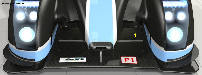
Also note the opening aft of the side windows. This is for cockpit ventilation and of mandatory area. | 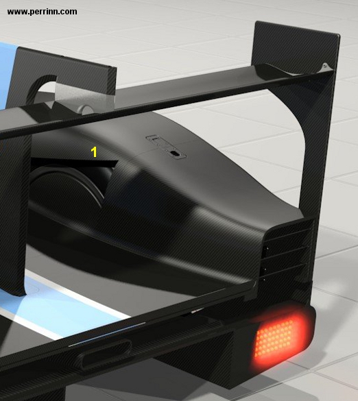 Also
recall the ACO2014 rules allow for two options when determining Big
Honking Holes, a top or bottom template for front and rear.
Apparently the ACO have rescinded their, "one or the other not
mix and match" mandate, as the Perrinn LMP1 runs top BHHs on the front
and inboard BHHs in the rear (1). Note it is essentially a slash
cut (of the prescribed area) but covers up the inboard face of the wheel. Also
recall the ACO2014 rules allow for two options when determining Big
Honking Holes, a top or bottom template for front and rear.
Apparently the ACO have rescinded their, "one or the other not
mix and match" mandate, as the Perrinn LMP1 runs top BHHs on the front
and inboard BHHs in the rear (1). Note it is essentially a slash
cut (of the prescribed area) but covers up the inboard face of the wheel.
Note the constant section, 1800 mm wide, rear wing. |
|  5.9.13 5.9.13
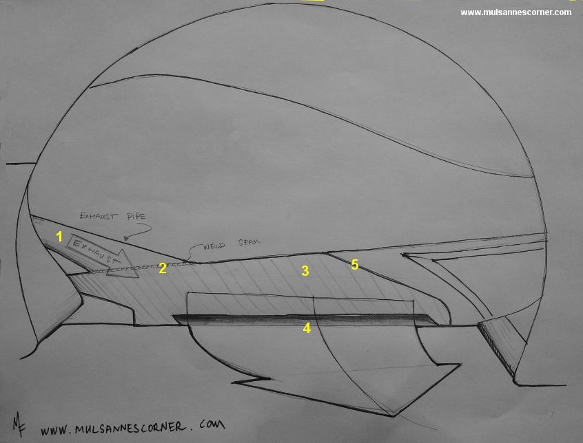
>>Another
day, some more analysis, and I'm now pretty confident I've figured out
where exactly the Audi's exhaust exits. Thanks to an image out of
Autohebdo (one that we really can't use) I've created the accompanying
sketch. I've removed the wheel from the shot, we're looking into
the wheel well, the rear of the car is to image right. We can see
the exhaust pipe doesn't simply end, it actually
plumbs into the outer edge of the underfloor (1) and, interestingly,
the actual exhaust pipe truncates (basically goes from round tube to
flat pancake) and then forms the entire outer floor section (3) in that
area. Note the weld seam (2). The exhaust outlet proper is
a slim elongated opening that allows the exhaust to exit (4). At
this point I'm assuming the exhaust turns 90 and points towards the
tire. But on second thought it could just as easily aim downwards
as the purpose appears to be to keep the vortex shed from the rear
wheel from entering the underfloor. Note the rear section parting
line (5).
These shots (1, 2, 3) showed up this morning on Endurance-info. |
| 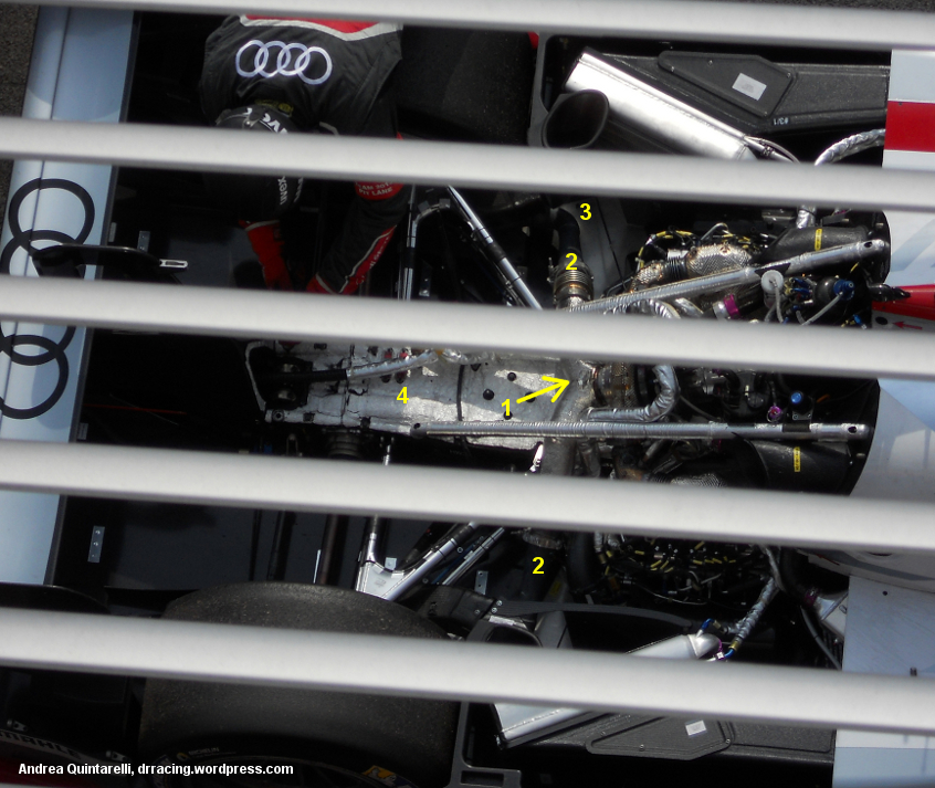 5.7.13 5.7.13
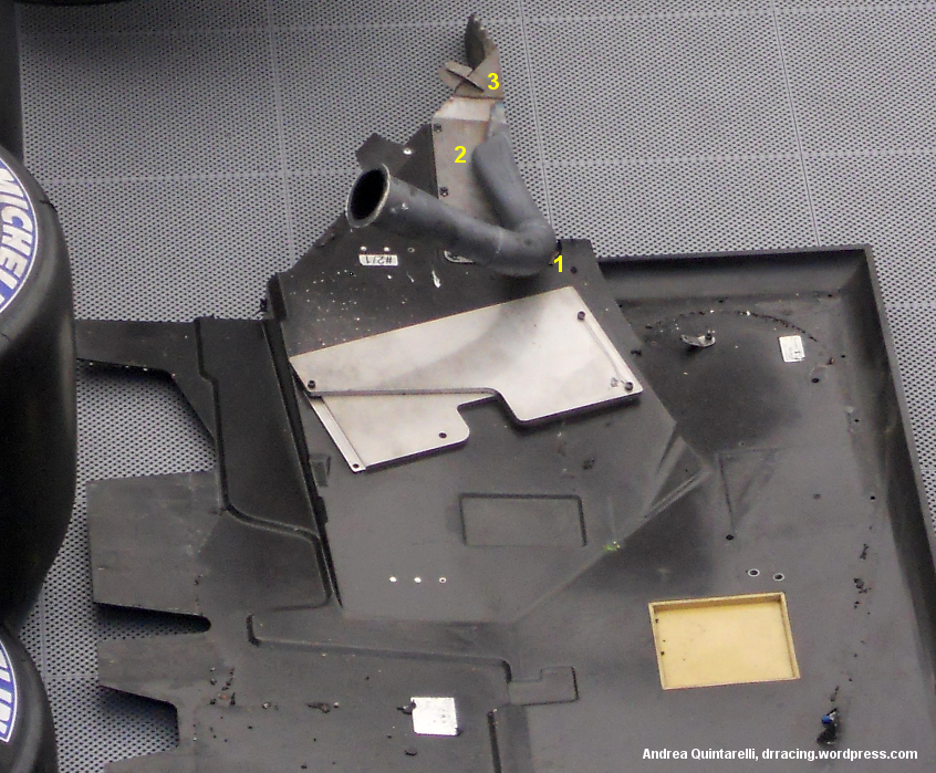
>>Here's a post-Spa Audi update. So I now have conclusive proof of how Audi's "exhaust blown diffuser" (EBD) is executed.
Andrea Quintarelli, of the blog DR's Racing Blog, was totally on it this past weekend and provides these shots. In
the first shot we're peering down on top of the R18 (great perch Andrea!),
ignore the annoying screen in the foreground. We can see the
turbo and the exhaust splitting into two (1) with each branch heading
towards the wheel well (2) and then heading south (3).
While we're here, note the extensive heat shielding on top of the carbon fiber gearbox just behind the turbo (4).
|  This
shot shows the left hand (car left hand) underfloor. Audi splits
their underfloor into left and right hand sections with a separate
trailing edge section. This
shot shows the left hand (car left hand) underfloor. Audi splits
their underfloor into left and right hand sections with a separate
trailing edge section.
Here we see that a section of the exhaust
stays with the floor. At (1) we see our southward bend (3 in the
above image). The exhaust plumbs directly into the floor (2) just past the leading edge of
the rear tire. And we begin to get an idea of what's going on
with the exhaust gases when we notice the amount of heat shielding in the general area (3).
But, even as I
show the images here, I understand a more descriptive angle is still
lacking and I'm told it might be best to request an image taken from a
lower angle....hint, hint.
|  Audi was good enough to place the rear ends for both the standard tail and long(er) tail R18 side by side. Audi was good enough to place the rear ends for both the standard tail and long(er) tail R18 side by side. | | Standard
tail R18. Focusing on the rear wing. Obviously Audi ran
different total downforce loads at Spa, if only evidenced by
the drastic difference in rear wing main plane and flap angles.
|  | | Long(er) tail R18. Note the flap chord is much shorter and it would appear the main plane section is different and the chord longer. |  |
|  A
close up of the Long(er) tail R18. Note the much larger
underfloor trailing edge extension (1). While a previously noted
detail, the rear wing mount is interesting as the load paths diverge to
make way for the now-obsoleted single exhaust pipe. A
close up of the Long(er) tail R18. Note the much larger
underfloor trailing edge extension (1). While a previously noted
detail, the rear wing mount is interesting as the load paths diverge to
make way for the now-obsoleted single exhaust pipe. | |  5.2.13 5.2.13
>>And I reveal the 2013 Toyota TS030 Longtail...
*Oh, what? Huh? Toyota has always
run their rear bodywork out to the 750 mm? So is it, or is it not
a long tail? What? Ruling on the field? Toyota's PR
department says no? Ok. So what are we calling it? Just 'Toyota TS030'?
Ooookkkkaaaayyy. But Audi's tail is no longer than the
Toyota's? Thus, inversely, the TS030 is a longtail as well, yes?
So what makes Audi's a "long tail" and Toyota's not? The rulers are longer in Germany?
Whhhaaaatttt? But both cars are made in Germany! I
don't think you know what you're talking about! Ah shit, I give
up.*
I take the piss! Sorry Audi, here's Toyota's Spa car! | 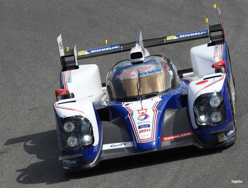 The first thing to notice is that Toyota will be
running the rear wing extensions at Spa (and presumably at Le Mans).
Toyota has significantly lowered the mainplane (1), with the wing
extensions following but still offset up higher than the mainplane (2).
The inner "primary" endplate height has followed the mainplane
downwards (3) while the outboard endplates are as tall and large as
they ever were (4), and still 'S' shaped. The first thing to notice is that Toyota will be
running the rear wing extensions at Spa (and presumably at Le Mans).
Toyota has significantly lowered the mainplane (1), with the wing
extensions following but still offset up higher than the mainplane (2).
The inner "primary" endplate height has followed the mainplane
downwards (3) while the outboard endplates are as tall and large as
they ever were (4), and still 'S' shaped.
The primary
take here is that the wing extension is of a much longer chord than the
regulations driven mainplane. And while the wing extension is an
extruded section (doesn't come to a point at the trailing edge), its
longer chord makes up for that in efficiency, especially compared to
the heavily regulated mainplane (chord and camber); the regulations
make the mainplane comparatively inefficient.
Therefore Toyota (and Audi) have taken advantage of unregulated
wing sections to run similar if slightly higher total downforce for
similar drag levels. This allows for a reduction in mainplane
height, angle-of-attack, and flap angle and the wing extensions
will generate a higher percentage of total wing downforce relative to
drag. Hence why we'll see them at Le Mans. | 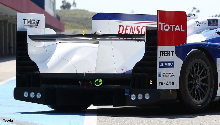 The
second item of note are the new louvers (1) that now reside just above
the legality "cheese wedge". These louvers work in conjunction
with revised rear wheel well exit ducting (2) . The initial
presumption is that these louvers could be drawing air for use in base
area infill. And I still am holding out that we'll see Toyota's
"blown diffuser" (here used as a term describing any
use of the exhaust for aerodynamic purposes) execution at some point.
That is, if the rumor is even true. The images Toyota has
revealed here show their conventional top exhaust exit. But the
reason I bring the exhausts up in the same breath as the louvers is
that one could see exhaust gases being ejected into this new base area
infill duct in order to help draw even more air through the louvers.
Anyone remember Andy Thorby's contribution to the Lister LMP1? Anyhow, just a thought. I'm not discounting the Toyota blown diffuser until Le Mans. The
second item of note are the new louvers (1) that now reside just above
the legality "cheese wedge". These louvers work in conjunction
with revised rear wheel well exit ducting (2) . The initial
presumption is that these louvers could be drawing air for use in base
area infill. And I still am holding out that we'll see Toyota's
"blown diffuser" (here used as a term describing any
use of the exhaust for aerodynamic purposes) execution at some point.
That is, if the rumor is even true. The images Toyota has
revealed here show their conventional top exhaust exit. But the
reason I bring the exhausts up in the same breath as the louvers is
that one could see exhaust gases being ejected into this new base area
infill duct in order to help draw even more air through the louvers.
Anyone remember Andy Thorby's contribution to the Lister LMP1? Anyhow, just a thought. I'm not discounting the Toyota blown diffuser until Le Mans.
The notched rear wing flap center trailing edge (3) is back. |
|
|

